Scheduling parts and purchasing for manufacturing projects
- Agnes Sopel

- Apr 10, 2022
- 7 min read

Manufactured and purchased parts for manufacturing projects lead to different problems. These are often associated with purchasing bulk materials.
Parts scheduling requires close analysis of drawings and specialised techniques. Any system of parts scheduling demands the assembly of data structured around BOM (Bill Of Materials). The scheduling, therefore, generally cannot take place until the design is substantially complete. That information must be derived from the project plan using critical path networks or bar charts. Scheduling on a much greater detail needed for individual parts should be done by the manufacturing organisation. These might consist of a list of components and labour required.
The parts scheduling step is usually quite complicated because some parts might be used for other projects.
Complications also arise when project has to result in more than one similar batch outputs produced in different times. Products might be in different stages of production at the same time. Engineering changes can also be expected affecting them. It can be managed through collating all the known part requirements, listing the assemblies and subassemblies on which the parts are to be used and relating the information into a project plan.
Parts scheduling example
For example, a company has designed a filling cabinet made of steel. All the parts of the cabinet can be listed in Bill of Materials (BOM) as presented in figure below.

CAD systems are often used for design as in the figure below.

Based on the component lists the company purchasing and production department will be able to buy and make the assembly. There is no complication here as everything is listed in the parts list.
If the completion date is given for making the cabinet it should be easy to know when the parts should be ordered. Priorities are given to those with longest lead times.
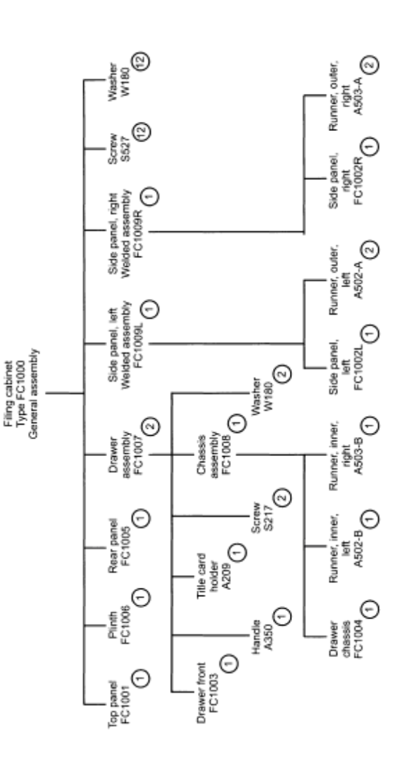
However, the production department might find the part list not useful, because they would need a separate part list for each sub-assembly. To produce those separate parts lists it is usual to draw a family tree showing all the sub-assemblies. This is a very detailed hierarchical structure as presented in figure below.

The level of detail here goes to a very lowest level, including every nut, bolt and washer. Further each level needs to show the quantity of each item needed. As the figure above presents four separate subassemblies have to be made before final assembly. This means that a simple part list must be designed for each separate lists of components. This is presented in figure below.

While this grouping is helpful for manufacturing process, it might not be helpful for purchasing department or scheduling of maintenance of parts. Some pats may appear twice in separate assemblies. If manufacturing requires of 10 different drawers the number of each components should be added accordingly to determine the total components required.
Complex parts scheduling
The process of parts scheduling might become more complex when more than one project is being undertaken at the same time. The same parts or assemblies might be required for different products.
Let's say, that we need to make 50 of the filling cabinets. Below figure presents the order quantity of each cabinet from customers.

To create a manufacturing schedule for all the batches it is necessary to reconcile the quantities of all parts needed with the complex delivery schedule.
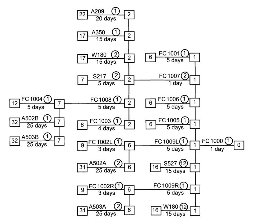
We can use a line of balance calculation. The first step would be to obtain a family tree for parts needed to produce one product. This will require to re-draw the family tree of individual product from left to right sequence. This is presented in the figure below.

The numbers provided in little circle of each part represents the quantity needed to assembly one filling cabinet.
The next step would be to add squares at every intersection at the end of tree branches for each item lead-time and the day the part will be needed must be estimated. These are total duration estimates. All activities such as issue of order, machine settings time, suppliers lead-times, shipping times have to be allowed for these times. Each estimate has been written below the branch in working days rounded up to the nearest whole day. This is now presented in the below figure.

Now the total project lead-time for any part can be found by adding up the individual lead-times backwards through the tree working from right to left. These are showing in event squares. For example, part A503B - two of these must be provided and they have to be ordered at least 32 days before the filling cabinet is wanted. If they are not received by the 7th day before completion is due the program is likely to run late. Everything on this tree is critical. All times are latest times. No float exists anywhere.
The delivery commitment graph can be shown as per figure below.

The figure shows the graph for the cabinet project. The time is scaled in working days starting from day 0 which is the first day of the delivery schedule. This way it is possible to know how many parts should have been ordered but also how many parts from the order must be available in stock or already used. This can also be presented in a chart form.
Each separate item might have dedicated column to itself and the total minimum quantity required can be shown as a horizontal line drawn up at the appropriate scale across the relevant column. These quantities are the necessary balance quantities for the programme.
The last step would be to find out what the actual progress is. Achievements which fall below the lines indicates that the delivery schedules have slipped and customers will not receive their cabinets on time.
Some inexpensive items might be purchased all at the same time as they also take up a little storage space. Separate charts can be designed for each day of the project.
The lines of balance cannot show reasons for shortages, but they are effective visual displays. They are useful for showing higher executives at meetings where deficiencies and time savings are. Example for line of balance for day 4 shows in below figure.

The charts can be further split to manufacturing operations and not only parts schedules. They could have allocated columns on the chart.
Computer industries have already recognised needs for such calculations. These have resulted in different techniques being developed, for example MRP (Materials Requirement Planning). These systems need a considerable amounts of data. Family tree analysis, parts collation and scheduling is automated.
Purchasing and material control
Purchasing is a vital part of every project. These generally account for halve of project costs. Insufficient purchases might wreck project profits and delays in manufacturing or project deadline. If goods are purchased long before they are needed funds might be locked in stocked raw materials. Material shortages may delay projects it may also damage the cashflows.
Purchasing functions may involve establishing acceptable vendor lists and assessment of their performance. In fact, procurement of any item can be treated as individual project in itself. Purchasing agent becomes the project manager.
A typical process is presented in figure below.

The process is initiated by requirement for raw materials, components and large equipment. It can be derived from engineering drawing, stock control or production control. Purchasing department is than asked to obtain a detail of suppliers, prices, delivery promise as well as expected performance. Then, a responsible person's signed off purchase order is made. This can use either purchase requisition form, Bill of Materials or parts list, stock replacement request for replenishment of stock.
The buyer will need to select supplier with acceptable quality of goods, price as well as delivery performance. The more specialised items the less suppliers might be available. When time allows, prices from different suppliers should be obtained and the lowest bidder chosen. Bearing in mind the quality, delivery performance and commercial standing.
In the next step an order is issued and sent to supplier. Order is typed and printed, signing and mailing to supplier. This activities might take time, therefore project management is concerned with it. Procurement lead times must always account for those types of delays. Generally two weeks is the estimated average time for procurement activities.
In the next step, the supplier would be obliged to acknowledge the order receipt, accepting the terms and confirm details of quantity, description, price and delivery. These details are generally included in the supplier quotation and the buyer would question any discrepancy. The binding contract exists as soon as the order has been accepted by the supplier.
The purchasing department would then communicate and control the supply. Often early warning systems are set to avoid delays and communicate with suppliers effectively.
Then, the goods are being delivered. This part requires regular inspections, even for possible lost items of damages in transit. Sometimes inwards inspections check goods more thoroughly to check they are matching the specification.
If the goods are accepted the goods inwards personnel may issue goods inwards certificate or copy of supplier despatch note. One copy will go to account department which is needed before paying supplier's invoice. Another copy will go to supplier's department to close off the file.

Rejection notes might be issued if a product is not accepted. But, if correct goods have been received, goods will be transported to stores.
Many businesses standardise their commercial conditions of purchase. Each company should seek their own legal advise to draft those conditions. The conditions will generally include Definitions, Payment terms, Prices, Quality and Descriptions, Indemnity, Intellectual property, Loss or Damage rules, Changes in the work, Sub-suppliers, Rejections, Arbitrations, Time of completion, Title of goods, Laws of the contract.

When making purchases overseas it is also important to define the responsibilities of international trade. Intercoms are one of the methods of setting those boundaries.
Bout-out parts can also often be specified by reference to manufacturers catalogue or part number. Manufacturers, however often secure the right to change the product. For example, changing a material or component. Preparation of special drawings for bought-out items is, however, perfectly justifiable. Drawings can outline dimensions, shapes, special requirements etc. These can also be used by goods inwards inspections and rectify any issues. Drawings can provide dramatic improvements.
It is important to identify those items that have a long lead times to ensure that ordering instructions are passed to purchasing department as soon as possible. Advanced purchasing instructions should be on the critical path of the project management.
Just-in-time system relies heavily on the suppliers to deliver goods on time. These are generally developed to reduce the stock holding to zero. Late deliveries are always one of the biggest risks for project managers, therefore we must always allow for contingencies.
Sometimes deliveries can be made to take goods in batches, these are called call-offs. The practice is rather common, especially for short life items. The goods are called off as they are needed for a project. This is particularly useful for larger projects where space and item risk damage. This can keep the inventory down and improve cashflow.


Comments